Monday, March 30, 2015

Punishment :: Foxx Tone Machine :: Work in Progress #4

After I've spray painted and drilled the enclosure, I went ahead and put the circuit inside.  I'll have to provide more details later, but of course it took a little bit of working out with alligator clips before hand.  I'm still working out the clipping diode differences.  Right now I think it sounds great with no clipping in the tone stack as well as with some diode clipping.  Once again a critical error on my part having made artwork before I tested out functionality of the circuit.  I don't know... to my ears, I don't hear much difference between the Ge clipping and the 1n4148 clipping.  So i tried it with Ge and LED clipping.  Sounds pretty cool, but I think I'll need to get a on/off/on switch so that I can have no clipping as an option as well.

Sunday, March 22, 2015

Punishment :: Foxx Tone Machine :: Work in Progress #3

So here I have printed on two enclosures and learned a couple of things. These are the first two color enclosures I've ever done, and herein are some tips that will make things easier in the future.

1.) LINING THINGS UP: As you've seen in the previous post, all the secondary text is a different color but also placed in different positions on the screen.  THIS IS AN INEFFICIENT IDEA!!! I thought it was going to work, but it resulted in a lot of drying the screen and trying to line things up.  For the next round, I think it'd be better to have all the secondary text lined up as it should be screened.  This will help you only have to make one pass and know that the image will be lined up as it should.  You can really tell on the Red image that the  Ge/Si diode section is tilted.  Try as I might, it was hard to gauge how "straight" the image lines up after you've masked off other portions to not have any paint go all over the place.

2.) COLOR: I really like the sparkle color paints that I have.  For the base color, I used a silver sparkle paint (I think it looks cool, and the paint was easy enough to work with).  However for the secondary color, I chose copper sparkle, which as you can see (or not!) is that the contrast is not deep enough between the silver and the copper.  It is very difficult to see against the silver.  But this is OK since the copper one is for me, and the red one is for a friend.  But it raises some questions about my color choices for other duochromatic pedals.

3.) BALANCE: This one kind of goes in with the color portion above, but looking at the pedal, there is an imbalance in the colors used (imo).  I think that a little bit at the top, and a little bit at the bottom, as well as the so called bulk in the middle would look a lot better. I think I would change the "BLACKSKYCRAFT" to the secondary color, and the "OUTPUT 9V INPUT" to  the secondary color as well.

So with those three things in mind I think for the next pedals I create I'll try to make sure that I create a better system of lining images up.  It might require me to buy a second screen, but I'll just have to see. I'll probably post again about how I do it.  In the mean time I'll need to wait for a dry weather day here to go over the enclosures with a clear coat and then later on down the line start the drilling process.

Punishment :: Modified Foxx Tone Machine :: Work in Progress #2

Alright so the weather was decent enough this weekend for me to proceed with the screen printing portion.  So I tried to document as much of the process as I possibly could starting from the beginning. So i scrapped my existing screen by removing the emulsion and voila! here were (ignore the image that is stained on the screen, any paint that passes through will change the color of screens over time)
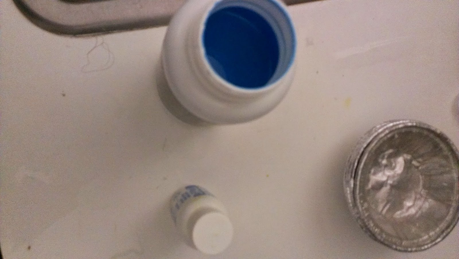
For this process you'll need Emulsion, (The larger white container), Photo Sensitizer (the small white container), and a squeegee (the red scraper). The quick explanation is that the light sensitive material will harden when exposed to light and anything not exposed to light will remain water soluble and we can wash it out.  But first things first: Preparing the Emulsion:

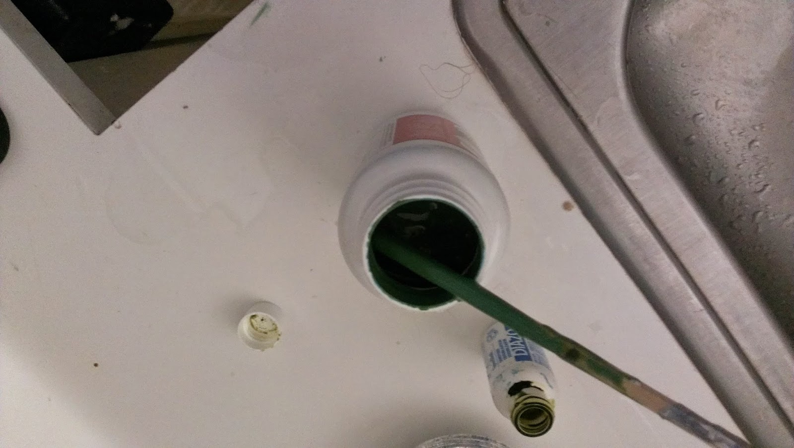
Before we can use the emulsion, we need to mix in the photo sensitizer.  There are differences across brands, but for the most part I've been using Speedball.  The emulsion starts off as blue, and you'll need to open the small photo sensitizer bottle and fill it half way up with water and mix it up thoroughly.  Then put it into the blue emulsion; this will cause it to turn green.  At this point in the process it is OK for there to be light in the room, the bottle is covering the emulsion for the most part, and of course you'll need to be able to see what you're doing. 

Stir it all up with a stirring stick of sorts, I have plenty of chopsticks from take out restaurants so I use those.

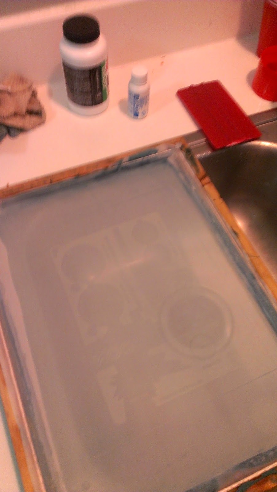
Now that we have the emulsion ready, we'll need to apply it to the screen.  Put a small amount on the screen.  What you see in the picture above is actually more than enough.  You want to have a thin layer that covers the screen with no excess. This takes a little bit of time to get used to, any extra emulsion can be returned to the container.
After you have gooped it onto the screen, take your squeegee and smear it across the screen. you'll want to press into the screen and slide up and down.  The process generally starts as just trying to get it to cover all corners of the screen.  After you have done this, work on getting the excess off,  Just scrape upward and then either wipe the goop off on a paper towel or try to get it back in the container.  DO that over and over, and switch to both sides. THE GOAL IS TO GET A THIN FILM TO COVER THE SCREEN AND NOT HAVE EXCESS ON EITHER SIDE.  With that in mind you should be able to get it down.  After you have smeared a thin layer across the screen, put it aside in a dark place for about an hour and a half.  I use the top shelf in my closet since it is flat and dark.

Onward to the next portion!!! Here is the printed screen on a transparency laid over the enclosure so we can once again see that it lines up and when we place the image on the emulsion it will be the right size.  BE CAREFUL ABOUT PRINTING ON TRANSPARENCY!!! IT CAN RUIN YOUR PRINTER!!! you'll either need a special printer or special transparency.  I personally go to Kinkos or UPS to get them to print out transparencies, that way the can keep printing until the scaling is correct. As you can see it looks like it did work out.

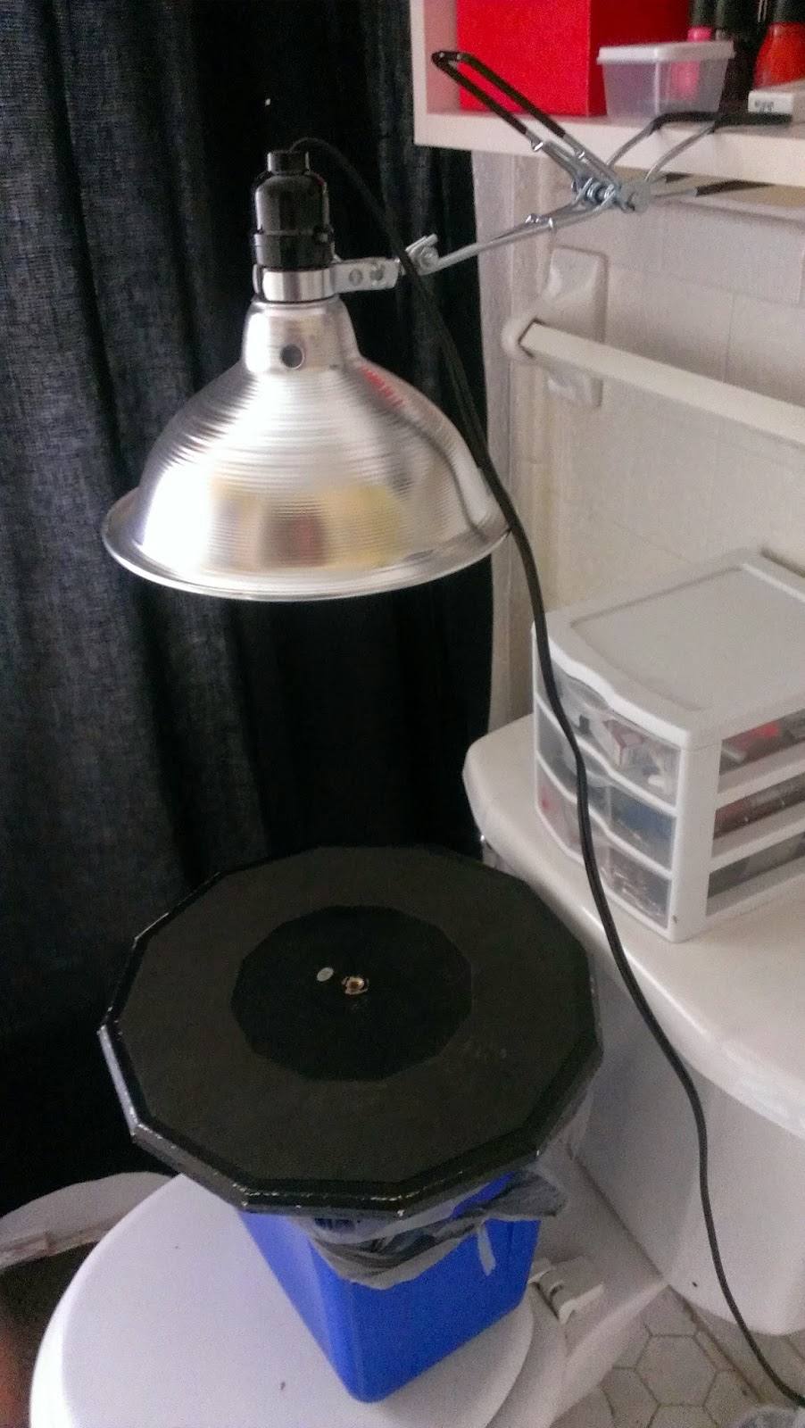
 You'll need some sort of set up with your lamp to be ~12-18 inches above the screen.  I use my bathroom since I can turn the light off and the lamp will be the only light source.  I'll detail more later on the type of bulb I used, but i bought the hi wattage bulb and the clamp at Home Depot for about 10 dollars. (you don't have to shell out the money for the Speedball kit in case you're wondering)
So as you can see its basically a trash can on top of the toilet with a black peice of wood on top.  I use the backside of my old drum practice pad.  It is black and non-reflective so that there is no interference of reflection on the underside of the screen messing with the image.

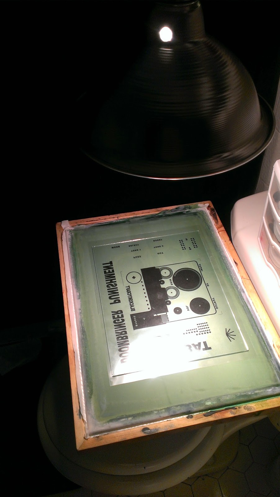
After the screen has cured you'll want to make preparations in the dark and put the image on the screen backwards and line it up underneath the lamp and then turn on the lamp and let the image sit for about 10-12 minutes.  The reason that you do it backwards is so that when you holding the screen up you have the "tray-side" of the screen looking up at you.  really it doesn't matter so much, but its just a bit of a guide from what I've learned.

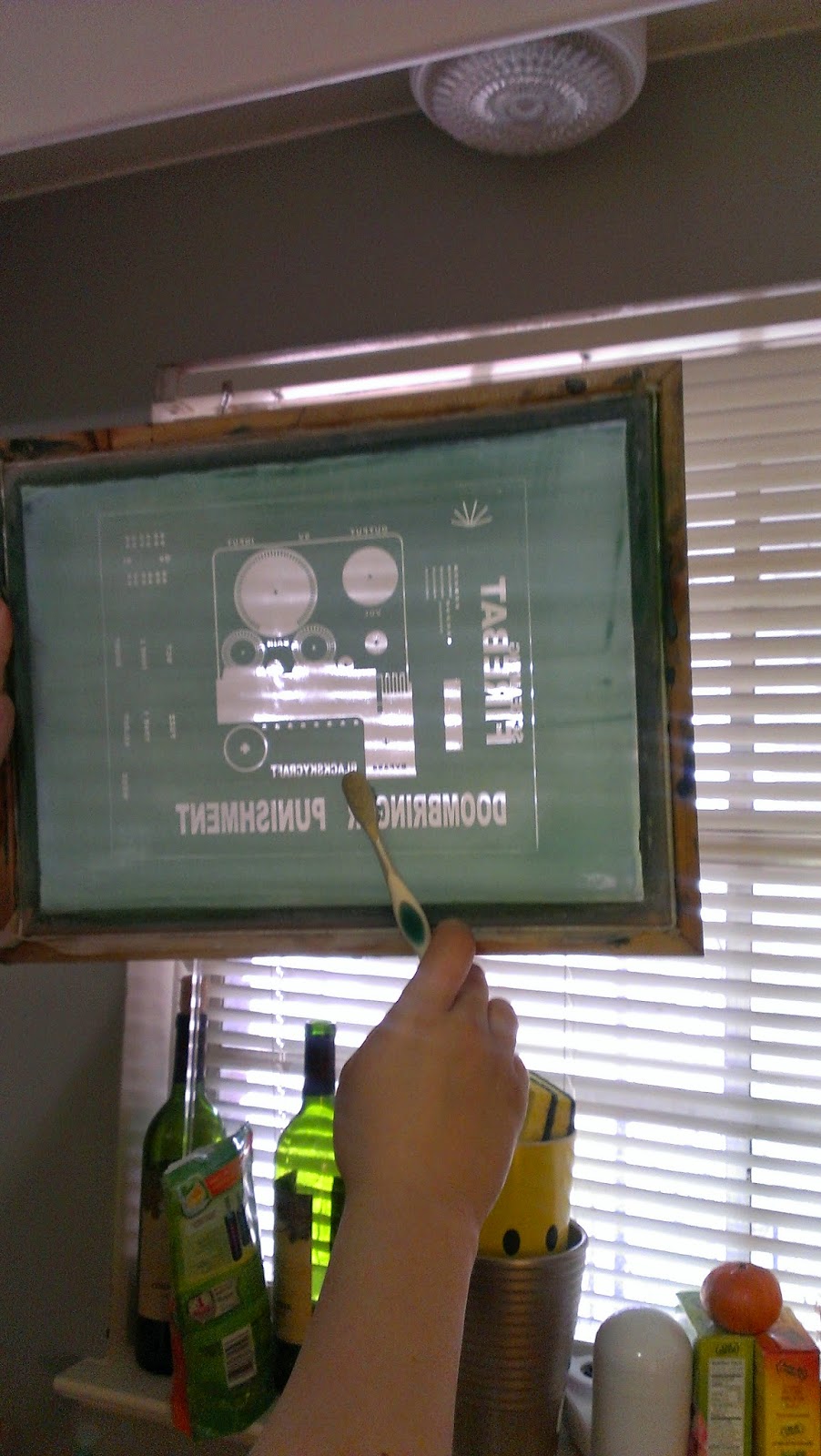
 After the 10-12 minutes are up you can turn off the lamp and take the screen to the sink.  You'll want to use an old toothbrush to really scrape out the goop under luke warm water.  Here is where you'll really see how the light sensitive emulsion works.  All the spots that were not exposed with light will be washed away.
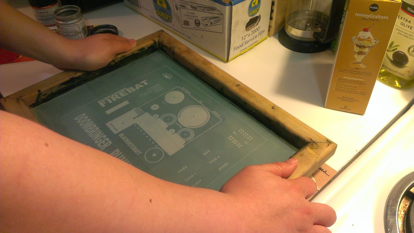
As you're scraping away, hold it up to the light to see how well you are scraping the emulsion out.  If you don't remove all the emulsion from the area that you want then it will result in the printed image.

After you've cleaned the screen to your satisfaction, you can put it back under the lamp for a couple of minutes to harden even further.

Use a hair dryer to dry the screen (alternatively you can let it sit for a while).
While you're waiting go ahead and spray paint the enclosure(s).  I'm still learning how to spray paint, but if I have learned anything, its that you should go light on the spray paint and go over it multiple times.  In the above image I've only gone over the enclosure with one pass.  Even still I had some runs on the vertical faces.  Once you have them sufficiently covered, let them sit for two hours or so and keep them away from dust/pollen/dander/cats, etc.

 Now onto the part we've all been waiting for, the printing portion!!!  Here is what I've set up to use.  The painted enclosure is on some scrap paper and flanked by two 1590BB enclosures without the bottom plates.  The aim here was to have the black enclosure sitting a little higher than the 1590BBs so that the screen can be securely held down against the enclosure without stretching the screen too much.
As you can see, just setting the screen on top of the black enclosure, there is a little bit of height clearance.

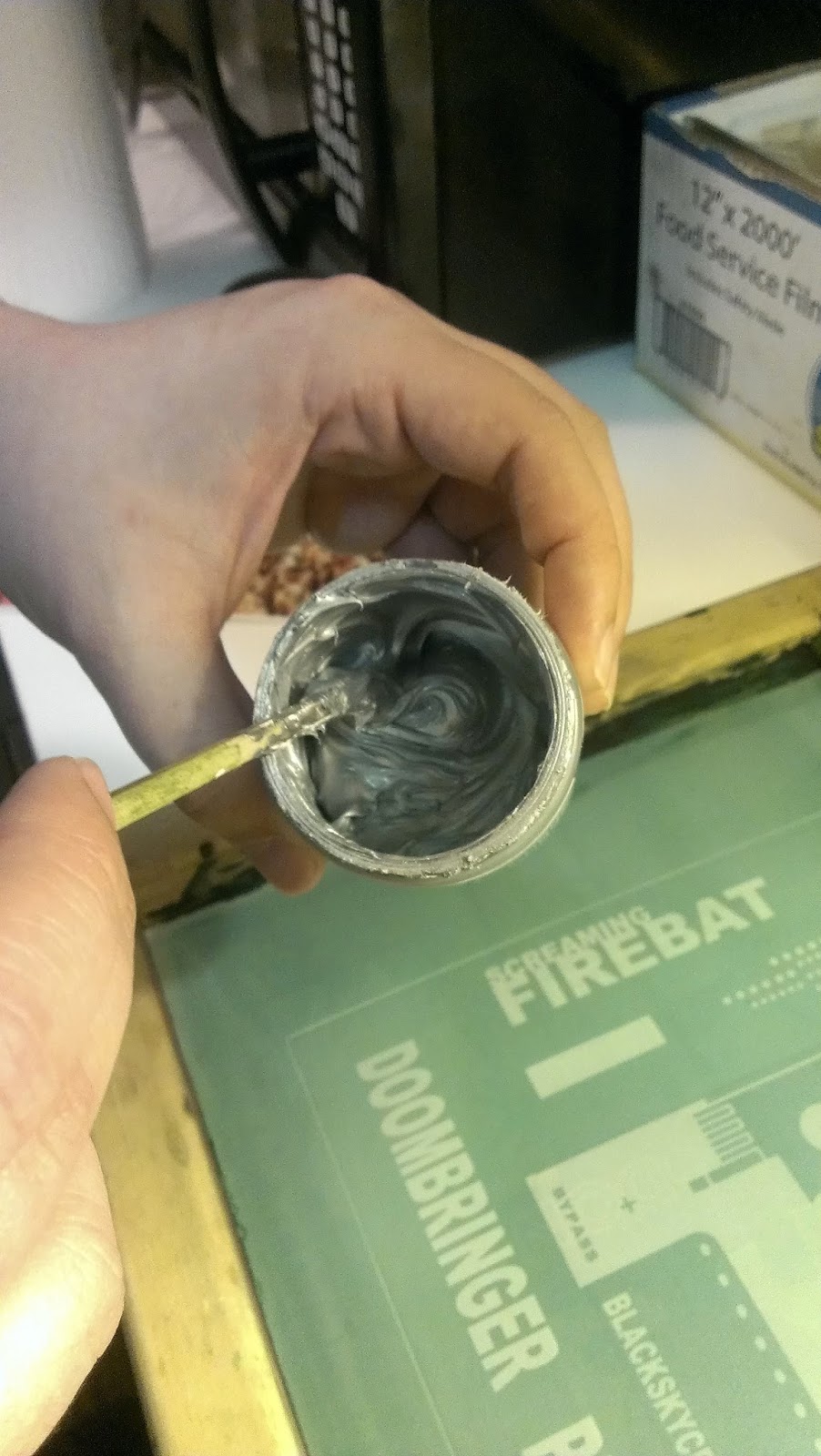
The next part is where you'll need an extra set of hands to hold the screen down tight against the enclosure.  At some point I'll make a rig to hold it down, but in the meantime I get help.  So I line up the image with the screen and then prep the acrylic paint.

Stir up the paint....

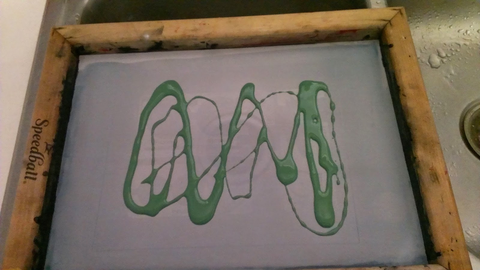
and dab a decent amount onto the top of the image. where you are going to print.  The next portion doesn't have any pictures since there were no extra hands to take pictures.  but basically its similar to the screen preparation portion, where you scrap down, up and across trying to get an even amount of paint to go across the image. 

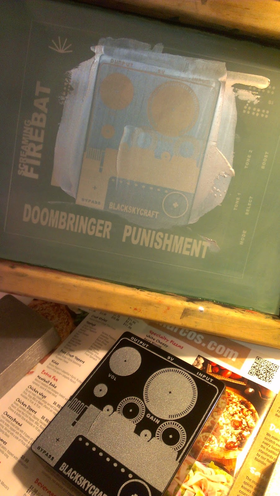
Here is an example of what happens when you leave a smear on the screen and then remove the screen from the enclosure. This is OK because this is for me, but if you're doing this for other people you'll want to avoid the above situation.  As you can see on the screen above, there is a weird wave going across screen image, and on the enclosure you can see the weird wave, it is caused by there being an abundance of paint on the screen as you separate the screen from the image....

...But as you can see it's not that noticeable, and when you're doing it for yourself it looks OK.

Saturday, March 21, 2015

Punishment :: Modified Foxx Tone Machine :: Work in Progress #1

So I thought I would finally put something up for the "entire" process of me assembling a guitar effect pedal. So here goes something... this is by large an effort to try to make adjustments to the existing effect, inspiration comes from Laowiz/superglops/Rob McIntosh.  If you haven't had a chance to check out his etched pedals, then take a moment and behold.

For the most part I already had in mind the effect I was going to use, so that made the artwork part relatively easy.  After finally hearing what the Foxxx tone machine (FTM) actually sounds like, I though it was rather interesting pedal and one that I'd like to try to build upon.

Having read some reviews of it, there were some complaints about the tone settings, in the base circuit there is a single tone control for both fuzz and octave settings, so I tried to change the filter controls when you change between settings.  In addition to this, there is diode clipping in the tone control circuit using germanium diodes, so why not make it on-on-on switchable for no and silicon diode clipping as well?

So to make long story short, I wanted to create a duochromatic base graphic that I could use, with options for labels that could be used later on for 3 pedals which I have multiple PCBS for (BYOC Mouse, BMP, and now FTM)
Here is the graphic that I'm currently working with...
Some things to keep in mind when working with this as i've learned is to make sure you measure things accurately!!! if you are using information on line, make sure you understand which part is being measured.  There are plenty of times which I have had to go back to the printer and re-print images because it is incorrect.

The method that I'm most comfortable with at the moment is screen printing, so I'll try and provide a little background for those who might be curious later on.  But you may or may not have to color invert your image so that the ink goes where you want it to.

After you have confirmed which image you want to use, you'll need to print it out and size it up. to make sure that your knob measurements and sizes are correct.
Based on the two preliminary design I was working with, this is somewhat along the lines of what the pedal should come out looking like.  The gain control was really measured for the specific knob on the left, but I as just playing around with out it looks.  I like both of images on the left and right, but I'm leaning more towards the image on the right.  I like it because the LED placement is a little more straightforward for determining which channel the effect is on. 

Have seen that things line up, its time to start working on the enclosures.  This picture probably doesn't show it, but the first thing you need to do is sand it down, and medium grain sandpaper should do, you just need to remove the excess gunk that is on top of it (left enclosure), and rough it up enough to give the spray paint something to grab on to.  As a word of advice, I would say to keep the sanding motion in the same direction, you will see scratches, and it will look weird if your scratches go all over the place.  I have yet to test whether or not it enhances the ability of paint to adhere to the metal, but from my eye it looks strange.

Here are the enclosures all cleaned up and ready for spray paint as soon as the weather permits.


Sunday, March 1, 2015

Still in there

Whew its been a while, my schedule has been busy but I've made some progress which I'll be updating shortly.
I've been working a lot with the Big Muff circuit and have created some variations for it which I think make it quite an interesting pedal.  I'm in the process of looking into an Octave fuzz stage but I learned that germanium diodes in this setting need to be matched in order to work out.  Right now I am experiencing a good bit of voltage drop when I using that part of the circuit.  I've run out of germanium diodes and have yet to look into buying more.

Also I've got a Foxx Tone Machine I'm working on which I'm going to try and have different EQ filters for the two different modes.  I am looking at upgrading my phone in the near future and should be able to provide some images soon.