Sunday, January 31, 2021
AND/OR Switching Part II: Active and Passive components
Sunday, January 17, 2021
AND/OR Switching System\\ Part 1
Part 1: The Gestalt
Saturday, January 9, 2021
Beginning with The End
There are a couple existing projects I want to finish up and others I want to update and expand on. In no particular order other than my thoughts at the moment, here's what I've got planned for the year.
1. The AND/OR switching system is under development, and is somewhat of a priority since I have a fetish for dual channel designs. Moreover, I think my future designs will require the use of micro controllers to accommodate the ideas I have in mind.
If I can get this to work, I'll document the process for those interested. For two-in-one projects it just seems like it would be a cool option to switch between A or B, A->B, and B->A in with a simple interface..
2. I will be revisiting the Solaris this year. Belton has a new brick coming out that should be interesting to work with. Its based on the Cool Audio multifx chip, but at least it doesn't require me to do any SMD soldering.
3. I have been wanting to do a tremolo pedal for so long and I think I have some ideas. Laowiz suggested I try out the Gristleizer, and I think I will start to breadboard that. I've seen some cool videos and of course the VCA/VCF modes fit nicely into my fetish :)
While learning more about microcontrollers, I may try and put out something for a
4. Modular Interfacing Longterm Fuzz is something I have been toying around with. Mostly to satisfy my crusade for the ideal fuzz for me. This will probably take the longest time to develop and may never be complete, but the basis of it will involve microcontrollers to simplify my life.
I don't want to get too far ahead of myself 4 projects for the year sound doable. The beginning always starts out strong, and right now since I have been drawing schematics and breadboarding most of December.
All along the way I'll put out some updates for the projects; the microcontroller work especially. I think it'd be nice to see simple microcontroller projects pop-up for other guitar pedal hobbyists out there.
Here's to a productive 2021
Best regards,
Bradford
Sunday, October 11, 2020
THE END: Dual fuzz dream eater
So, I've been diving deep into the V1 Fuzz War again and again, and have another variant on the horizon. Last year's Dark Sun was more of a re-imagining with a harsher edge, but I was still looking to capture the thick fuzziness of the V1 Fuzz War and something close to the Silver Armageddon.
Well after a couple months of testing, tweaking, and re-testing. I have (re-re-re-)designed a functioning silver Armageddon. This was largely based on the gut shots from a known source and the values from tracing my personal V1 Fuzz War.
As an overview,
The End is a dual fuzz which allows you to select different filters via footswitch. In addition, there are two toggle switches, 1 to allow more or less low frequencies to enter at 2 points in the circuit, and one to switch between the original silver Armageddon, and a personal variant for the fuzz/filters.
I made some small tweaks to the design to optimize performance, but this pedal "The End" is supposed to be as faithful of a recreation of the silver Armageddon as possible. In the next series of posts I'll post more details about 'The End'.
In this post I'll talk about options for the notch filter also referred to as "Filter 1":
Here is what the silver Armageddon's notch filter looks like. It provides a very deep cut that can be shifted up and down the frequency range so that you can cut out lows, mids, or highs. The notch ranges from approximately 100Hz up to 1.1kHz with an approximate 50db cut.
Sunday, August 16, 2020
The Journey to New AND/OR...
While looking over how to improve the functionality of the Receiver Operator. It has occurred to me that there are a bunch of routing options that could make this pedal incredibly versatile. I took a look out at other companies who create multi-channel pedals and noticed a "gap in the market". There are a number of ABY switches out there, Lehle, Earthquaker Devices, Morley, EHX, to name a few. All of these are outstanding pedals in their own right in terms of straightforward use, or options galore depending on what you are looking for. However, I have yet to see a pedal which can do what I am looking for.
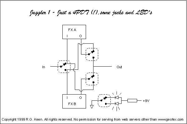
The RecOp and the pedals it was inspired by are known for their dual channel nature. Let's call this "OR", after the A OR B function of the operation. This is an easy to implement function using a 3PDT switch, which is what the new J Mascis Fuzz from the previous post most likely uses. The next step in the evolution would be driving A into B, and naturally following that would be driving B into A.
These aren't ABY type of options, but they aren't that different. The AB component remains the same. The Y option is not in question, although with the creation of one design, another is born. We'll tackle that at a later date.
So the three functional goals for this design are:
1. A "OR" B
2. A "INTO" B
3. B "INTO" A
Ideally, the end product would be simple enough to control with a 3-way toggle switch so that any body could drop this design into their DIY pedal and have a wide range of control over 2 different effects in the same box. Similar to the 3PDT/4PDT order switcher boards out there.
At present the RecOp can do Notch "OR" Boost, I have figured a way to re-route the signal as Boost "INTO" Notch, but the effects are not independent. In this first draft of the INTO mode switch, the bypass button turns the Notch on (which makes sense since it is on the left hand side below the Notch controls), and the Select button turns on the boost, which then runs into the Notch. If we only toggle Select, it does not engage the boost section. it just lets us know that when we do turn on the Circuit, we will be slamming the notch with the boost.
In my mind this is a cool feature, but it is not exactly where I want to go with this pedal.
The challenge at present is the number of SPDTs that have to be used and changing the LED indication status to reflect how the pedal is going to work. For the "OR" function I am partial to DBAs approach of having dimmed channel indication in bypass. For the "Into" functions (if they work as independent units) I don't think dimming is necessary, but a tri-colored LED would be nice as a sort of visual cue to which mode you are in. Albeit unecessary, LEDs always make things neat.
So I'll try and do a better job about documenting how I implement this and get more shots of the breadboard up in the meantime too.
Friday, May 29, 2020
Switches & channels
To start, I have always been a fan of having two channels on pedals, something attracts me to that sort of design. Probably my early exposure in pedals to the DBA soundsaw and kill kill filter.
Recently, there is a Big Muff by Wren and Cuff ("Garbage Face") that has been released which allows for two different volume settings for a channel.
I can't say for certain how they implement this, but if I had to guess it would be like the old Beavis audio, two pots on a stomp with an LED approach. http://beavisaudio.com/techpages/switches/
Not a bad approach at all! Easy to implement, minimum parts count and greatly expands the sonic pallete of a certain pedal. In fact the DBA KKF uses this type of control, to change the tone potentiometer. Move this over to the potentiometer for gain, and you can have two channels which allow you to vary the saturation of your dirt circuit. All of this with a 3PDT switch (Stomp or toggle pick your poison)
If you don't care for the LED indicator, you could get by with the DPDT. But wait!!! What about other options. As far as mechanical switches go, we can move up the the 4PDT. Which depending on how we want to implement it for channel switching, we could get creative and allow changes to be made to 3 controls of a circuit, but would need to isolate components so they don't interact across channels. I.e. the we don't want the volume control for channel one to change the volume of channel two. Digital switching systems are more complicated, but offer a longer life-span and the potential for more parameters of the pedal to be channel switched. This comes at the cost of more knobs to interact with though. Digital presets are the next evolution which allow you to have the base number of potentiomers and the ability to cycle through "saved" states. The challenge with this approach is not being able to see what the preset was.
The NEW DBA ROOMS pedal looks to have 3 channels switchable on their "ALT" footswitch. While there are large knobs for Frequency, Depth, and Time, there is also a smaller 9mm potentiometers for F, D, and T which I am going to guess is tied to the ALT footswitch.
This of course depends on how the potentiometer is oriented in the circuit to begin with. This is most ideal for potentiometers set up as voltage dividers.
This is brief post covering aspects of mechanical switches for "multi channel" modifications to your pedal, but also serve as a backdrop to part of the process going into the Sound Saw REMAKE. The pedal toggles back and forth between the boost and the filter sides of the circuit.
Saturday, May 16, 2020
Thoughts on the SoundSaw
Glad you could join me, now let us begin.
SOUND SAW
what was the deal with that pedal anyway? Crazy awesome sounding demos on the old DBA website, but they are hard to come by and there is one schematic that has been floating around for years now.
Back in 2014-2016ish, I was helping Glass Hero screen some enclosures with the Sound Saw artwork until he disappeared (hope all is well). It was about that time that my life got complicated and I had to put a lot of things on hold and move states to a new job, now after moving to another state for another job, I feel like building pedals again. I have been ever so slowly unpacking my tools and reviewing old schematics I had drawn up to try and start being a little more efficient with my design process.
Part of this process is putting out a SOUND SAW REMAKE. I am looking at the instruction card from the original and tasking myself to recreate a pedal like this. Something that has the same functionality, but with improvements based on my knowledge thus far and what I would want, and something that adds to the original
After looking through the forums and customer reviews and feedback, I hope to incorporate those ideas and create an excellent REMAKE. At the end of the day, I will probably email Oliver the results of my passion project and send him my REMAKE.
I have sent off for PCBs to test the backbone circuit of the pedal.
From here I will be developing the upgraded (deluxe) variant of the pedal.
I would really like to dig into some programming to make this process incorporate a challenge of a different dimension. Another reason is the relatively short foot switch lifespan of mechanical bypass pedals. With a pedal which you can toggle channels for huge variations in sound, a foot switch will most likely get plenty of use. Once it is all used up, what is the customer left with? a dead foot switch. Let's try and avoid that from here on out.
I'll keep you all posted as I move forward with this project.
After this I can get around to....reverb pedal REMAKE.
Best regards
Friday, April 3, 2020
Solaris reverb, feedback, and diagrams: Where the past listens to the future
Sunday, January 12, 2020
Madbean 2019 POTY contest entry
Thursday, November 7, 2019
DREAMEATER Dark Sun
Also there was a skeptical issue regarding the schematics that were floating around. So this time around I cracked open the pedal myself and started to trace it out only to discover that the circuit was different from the designs floating around.
Sunday, September 24, 2017
Solaris
Saturday, July 16, 2016
Baku Baku overdrive
The main goal with the PCB was to reduce my frustration with offboard wiring! So for this i used smaller board mounted pots and input/output/9v/GND pads that could be connected to a separate 3PDT stomp switch board. I bought some ribbon cable to use to make it look a little tidier than 4 separate wires, and I have to say that I am rather pleased with the ease of installation and how much nicer it looks on the inside.
In addition to this I wanted to give my pedal a little something extra with the presentation on the outside, so I used some contrasting hardware colors, as well as screenprinted a lion logo on the side. The screenprint on the side isn't my best idea, but somewhat of an idea of the direction I'd like to head with my designs so its not just good looking on the top of the pedal, but more so that all surfaces will have something interesting going on with them.
Here is the schematic for those of you interested in breadboarding this guy. The sound may not be for everyone but I dig it so far :)
If you breadboard it, please let me know what you think, or if you see any design issues which would improve the performance of the pedal please let me know. I'd really appreciate any feedback.
Monday, July 4, 2016
Another etched attempt
Sunday, March 13, 2016
Testing out etching
Here is what the mask looked like. I think I could have spent longer, it took me about 10 minutes of rotating it under the iron. My goal was to try and get the ink to show through the paper while I was ironing it.
I scrubbed it after it had been through its last rinse, but it still retained some sort of rust look to it. I can't seem to scrub it off, i'll have to see if it'll be an issue if I try and spray paint over it. However it does look like the mask didn't entirely protect what it was supposed to. Its all good, since I was going for a really beat up type of look. I have to drill through the holes first and then test out spray painting it.
After cleaning off more of the gunk with a green scrubby pad and nail polish remover it looks a a lot nicer
I was debating whether or not to coat it with anything, I got some great advice to clear coat it with stuff from the automotive department from Cody (CHECK OUT HIS AWESOME BLOG!), and another Madbeaner DMinner (MAKES SOME REALLY GREAT ETCHES) said it might be fine with out it. After holding the pedal for a little bit, it became clear that it was still rubbing blackness off onto my hands. So i used some of the Krylon Gloss Clear coat that I had around and laid it on there. In person the light hits the metallic flakes in the paint and it looks great!
And the guts
And testing out another one for a friend...
Wednesday, January 13, 2016
Simple switch between big muff and supa tonebender using Madbean's Mudbunny board.
lifting the miller cap will not do what we want it to do!
Basically we do is move c6 to be switched in and out of the circuit using an SPDT.
This is what was done for the "Screaming Firebat" pedal.
Sunday, November 8, 2015
Friday, October 9, 2015
reverse boosting
Tuesday, October 6, 2015
Getting back into screen printing
So this is my heavily modified big muff design with different clipping options.
Monday, September 28, 2015
Bringing it all home: the reason for blackcraft
So after thinking about it for a long time, I've decided to try and build the original 7 transistor fuzz war. this has reportedly given many people problems. Without knowing what they've done wrong I've decided to take a stab at building one myself.
I've got the schematic in hand and I've got some experience playing around with reverse transistor setups and have figured what the heck...
Here is the infamous 7 transistor schematic most people have probable seen. The starting point...