Showing posts with label Binary FIlter. Show all posts

Sunday, January 17, 2021

AND/OR Switching System\\ Part 1

Part 1: The Gestalt


   The ability to control two different effects is one of the joys of having multiple pedals or multiple effects. To date, I have focused most of my attention on switching between channels in a "parallel" manner. However, while doing research for the DBA sound saw and the Kill Kill Filter, it seems that users were interested in the ability to run one filter into another. The challenge ahead is how to develop a system which could accomplish at least 3 modes of operation (1) A into B, (2) B into A, (3) A or B, and (4) A and B.

    Here's a version of a generalized schematic diagramof the switching systems we're interested in with. It should be noted that (1), (2), and (4) could use different grounding methods depending on your preference. 


    I have left off the LED switching systems at the moment for simplicity. Regardless, moving from (1) to (2) can be accomplished in a simple manner using the Geofex Juggler Effects Reverser.
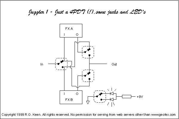


    What we can see from this is that in addition to the Switching system to turn each effect ON and OFF, we require an additional 3 (or 4) SPDT switches to change the effect order.

    So the challenge becomes mostly focused on getting between mode (3) and either mode (1) or (2). As well as getting to mode (4) and making sure that there aren't any phase issues. If we can draw out the paths to get between these modes, then its just a matter of a couple more SPDT switches to change the effect order.

    Herein lies four of the starting challenges I've identified thus far:
A. The number of SPDT switches required.
  We are already at 3 or 4 to just move between modes (1) and (2) NOT including the LED indication. Adding in mode (3), and it should be clear that there is probably not going to be an analog toggle switch or rotary switch which will be able to accomplish this switching. In addition, we will need a way to cycle through states in a relatively easy way.

B. Switch life time.
    Part of the fun of the OR configuration is the ability to switch back and forth between effects/channels to quickly switch between different sounds. This will result in the "Channel Select" switch getting pressed more than the "Bypass" switch. Like everything, mechanical switches have a lifetime, can get worn out, and die on us, which present challenges with replacing them. Normally Open (NO) momentary switches have been used to toggle states of relays for pedals and can be used, but we'll need a way to address the toggled status of effects after power is disconnected. This is notably a problem in the OR mode.

C. CMOS switching and pop.
    To accommodate the anticipated large number of switches, we'll likely need to use CMOS chips for switching. In my experience, there has always been a popping issue for me when I have breadboarded this. We'll need to include a form of muting system to prevent popping from being an issue when switching between the AND/OR modes when the effect is powered up.

D. Method of indicating which MODE we are in.
    Switching between 4 modes, pretty much eliminates a single toggle switch (e.g. ON-ON-ON) to select the mode. I believe the choice is between (i) a rotary switch, and (ii) a push-button switch that cycles through the modes with some additional LEDs to indicate which mode is currently selected. I am leaning toward the pushbutton cycle selection since it is a new area for me to explore and doesn't take up as much space as a rotary switch. In my experience with Alpha Rotary switches (both plastic and metal) is that they stick up higher than the potentiometers, and often times require additional washers or an additional nut to get the right spacing/height with the inside of the enclosure. The issue with LEDs is finding the optimal way to communicate with the user which mode is currently active.


    At the moment, the solution seems to be pointing toward a microcontroller-based solution. I'm pretty sure this switching system could be achieved to a degree without a microcontroller. But one of my goals for 2021 was to push myself in a different direction. I think that incorporating microcontrollers into my effects pedals will push me into uncomfortable territory but ultimately improve my creations.


Saturday, May 16, 2020

Thoughts on the SoundSaw

Hey team,
 Glad you could join me, now let us begin.

SOUND SAW
what was the deal with that pedal anyway? Crazy awesome sounding demos on the old DBA website, but they are hard to come by and there is one schematic that has been floating around for years now.

Back in 2014-2016ish, I was helping Glass Hero screen some enclosures with the Sound Saw artwork until he disappeared (hope all is well). It was about that time that my life got complicated and I had to put a lot of things on hold and move states to a new job, now after moving to another state for another job, I feel like building pedals again. I have been ever so slowly unpacking my tools and reviewing old schematics I had drawn up to try and start being a little more efficient with my design process.

Part of this process is putting out a SOUND SAW REMAKE. I am looking at the instruction card from the original and tasking myself to recreate a pedal like this. Something that has the same functionality, but with improvements based on my knowledge thus far and what I would want, and something that adds to the original

After looking through the forums and customer reviews and feedback, I hope to incorporate those ideas and create an excellent REMAKE.  At the end of the day, I will probably email Oliver the results of my passion project and send him my REMAKE.

I have sent off for PCBs to test the backbone circuit of the pedal.


From here I will be developing the upgraded (deluxe) variant of the pedal.

I would really like to dig into some programming to make this process incorporate a challenge of a different dimension. Another reason is the relatively short foot switch lifespan of mechanical bypass pedals. With a pedal which you can toggle channels for huge variations in sound, a foot switch will most likely get plenty of use.  Once it is all used up, what is the customer left with? a dead foot switch. Let's try and avoid that from here on out.

I'll keep you all posted as I move forward with this project.

After this I can get around to....reverb pedal REMAKE.

Best regards

Wednesday, September 17, 2014

The Double Filter Revisited: Junction Machine

Alright so I've come back around to working on the double filter pedal and have made it much simpler on myself.  Basically I have implemented a variable capacitor at the beginning of an LPB-1 with a footswitchable potentiometer to let me switch between boosting frequencies.  I socketed the two input capacitors and the output capacitor of the LPB-1. This basically makes it so that I can switch out the range of the frequency at a later date.  At the moment I need to go back in modify the range of the pedal.  Its looking like I need larger output capacitors to let more bass go though, as well as larger capacitors on one end of my variable capacitor.

If you've seen Kit Rae's big muff page, he has a lot of schematics on there.  The idea of using an input "Depth" or "Focus" is where this originated.  A quick glimpse at the Supercolyder is where I'll be heading next with the Capacitor selection.  I think having a 10uF capacitor at the output should be good enough to let all frequencies pass through, and having a 10uF and 0.01uF at the input capacitor will allow for a drastic range across the frequency sweep.

Much thanks to Micah over at Glass Hero for his help.  His website is down, but he makes some awesome pedals!! Check out his facebook in the meantime.


Saturday, July 26, 2014

Binary Filter


Alright I think I'm pretty close to completing this pedal.  The filter switching system works and the knobs do what they're supposed to do for the most part. The filter network is a little bit off. Because of that, the filters switch between potentiometers, but the bass side of the filter network doesn't quite sound right.  It has a gated sound to it.  Also after 12 o'Clock the filters start to let in some hiss.  The toggle switches don't do that much at this point. They help remove some of the hiss but I used the wrong type of capacitors.  I'm not sure how much at this point.

1.) Using 2n5088s transistors, but I need to check out the difference between those and 2n5089, as of right now this sounds close to a fuzz pedal already at max gain settings. Apparently 2n5088s seem to get fuzzy, whereas 2n5089s have more gain but retain a certain amount of clarity that the 2n5088s don't have.
2.) I have option of including a coupling polyfilm capacitor between the tonestack and the output section.
3.) I need to switch out the polyfilm capacitors in the tonestack for ceramic capacitors to see if this makes any difference.  Also a quick check of the filter networks will help me see what is going on with the Low pass filter.

Another idea based on this circuit would be to use two rotary switches to switch between input capacitors and just uses 1 filter network.  This would be interesting in that the initial frequencies would be somewhat filtered, and then further tailored in the tonestack.  So you could have 2 different versions of the same tonestack setting.

Thursday, July 10, 2014

Artwork for Pedals

I learned how to screen print out of necessity for my desire to clone pedals. However now getting into designing the graphics on the pedals I want to build, I've found that it has come in quite handy.  Also it makes putting images on shirts a lot easier than stenciling. So if you want your pedals to look interesting, coming up with the artwork and applying it to the enclosure is an excellent way to go about doing that.  There are different ways to get your labels onto a pedal. So far I've seen the following:
1.) Sharpie
2.) Label Maker
3.) Water slide stickers
4.) Hand painting
5.) Screen Printing
6.) Etching
Any of these above methods works, and they all have great potential to look really cool.  Screen printing is just what I've been doing and it happens to work out great.  There are some freeware available out there that would work great for creating the graphics you need. GIMP is one such program, I've been meaning to learn how to use it, in due time. Basically it's a comparable alternative to Adobe Photoshop.

  What I've been using is Microsoft Powerpoint.  It's familiar, simple to use, and create most shapes that you want, with some work on layering I've been able to mimic the abilities of other more notable programs.  In addition to this, most people have access to powerpoint, and if not OpenOffice is another open source alternative.  The great thing about powerpoint is that you can scale the images to the size that you want, usually you can get the color of the paint you'll be using.

Maybe at some point I'll do a video tutorial on it.  But in the meantime here are the tentative images I'm thinking on putting on my pedals.
I'm still trying to decide how I want the black stripe to look on the right hand side.  Whether or not to have a stripe or just the images. Luckily the only thing left is figuring out the placement of the DPDT switches.  Otherwise this pedal is pretty much good to go.

Overall I'm satisfied with the look of this pedal, however I'm just not sure about the clipping options.I was thinking about having a switch to have either some germanium diodes clipping the signal, or an LED clipping the signal.  I'll have to test it out but I think that it's feasible.  There will be a lot of room in this enclosure so I have the option of changing a lot about this pedal. 

Wednesday, July 9, 2014

Moving in and out of sound with Filters.

For all of you My Bloody Valentine fans out there,


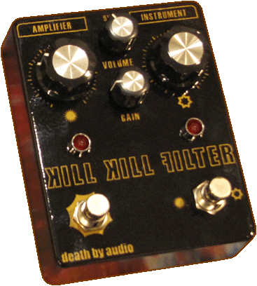
This is Kevin Shields' supposed rig from the Loveless tour.  At the beginning of his chain he has his primary distortion unit followed by 2 graphic equalizer pedals.  This is in addition to the 3-band EQ that is already in the Marshall Shredmaster.  So it seems that he has 3-preset tones that he can utilize just at the beginning of his pedal chain.  One of my goals is to make something similar to this.  It has been essentially seen in the Death By Audio Kill Kill Filter.  However There are some things about filters that I've learned in the meantime which I think could be added.


The generic Big Muff Pi Tone is what I plan on using in most of my designs, from what I understand it is both a hi-pass and low-pass filter which can be sweeped between the two. One of it's characteristics is the Mid-Range Notch, which depending on the music style you're playing may cause you to get lost in the band's mix.  With out a proper equalizer you might not be able to hear yourself too well.  One thing I've seen from the BYOC big muff clone is that they have changed some of the capacitor values in order to achieve the mid range notch, a flat mids tone, as well as mid-range boost.  This option has already been applied to the distortion unit, but I'd like to take it further and apply it to the dual filter idea.

What I'd like to do is to be able to choose the general mid-range characteristic, and then be able to switch between two sweepable frequency equalizers to further characterize the tone.  I'd like to have a little bit more options in terms of mid-range characterizations, so instead of a single rotary switch to choose between 3 mid-range options, I'd like to implement 2 toggle switches to choose from 4 different tonal characteristics.

I'll have to see how I'd go about doing this, I think a set of DPDT switches in place of the capacitors in the filter would allow for me to make the toggle switches work properly. Some LED's would be nice as well, probably 3mm as indicators of which characteristic option is currently selected so they don't compete with the.  I've got a basic layout created for this pedal, I'll just need to upload it...another saga another day....Duplex Filter something or other...