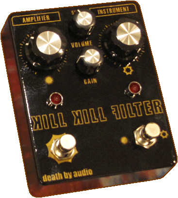
Alright, so I have not quite got the current Binary Filter to work. I messed around with the wires, testing just one capacitor per filter, and still it just goes from Farty to clear sounding, with little variation on the sweep of the potentiometer. It sounds interesting, but not quite what I had in mind. All of the PCB and wires makes up a giant rats nest which is hard for me to diagnose where I've gone wrong. Ultimately I think that due to my lack of knowledge in this area I'll have a hard time going through and assessing where things are going wrong. Heh I'll admit it was quite frustrating, this is the 3rd time I've attempted to make this circuit. Which leads me a very crucial tip.
MAKE SURE YOUR CIRCUIT WORKS EXACTLY AS YOU LIKE BEFORE YOU PUT IT IN THE ENCLOSURE!!!
Unfortunately for me I get too excited and map out the graphics for the enclosure before I have the circuit done and pretty much finish the enclosure before I've even tested the complete circuit. So now I am left with this metal box with wholes in it that I've got to make work for me, otherwise I end up with well, just another metal box with holes in it. Big picture here is to not get too ambitious with your first couple of circuits. On the positive side of things, my 3PDT switching has worked for my past 2 failed attempts.
Ultimately the idea is to create a dual boost pedal, where I can choose to either boost the bass or treble side of a signal. Which would allow it to work great with most any other pedal. I see this as a great sort of "support system" type of pedal.
So I'm going with the idea of just keeping things simple. Lets go caveman style! This should be a positive distraction to keep me from thinking about how much desoldering I'm going to have to do in order to salvage the components and the PCB. Since the first pedal was an LPB-1 in a pedal, I figured I'd extend my abilities from there. Apparently switching out the input capacitors on this circuit changes the frequencies that are allowed to pass. If i could load up a good number of those on a rotary switch then I think it would kind of function like a tone knob from the LPB-1/my signal. Add on a 3PDT switching system and I'm already getting started. For further tailoring I think I'll follow it by a Tone Stack and a recovery stage.
This is what I've drawn up so far.
I apologize for the blurry image, but my camera is messed up, and besides there are not values or even a tested version that I can tell you works at all. But you get the idea of what I'm going for. I think this should be more straight forward than the previous design and I believe should operate in a similar manner. The other issue is what to do with the two extra holes in the front of the enclosure. Previously these were for the High and Low pass capacitors, but now I'll have to come up with something else. (Once again this is where I'll have to continue testing out my circuit ideas...) But in the meantime onto the next paragraph.
Tone clipping is the focus here!!! For those of you who haven't been to the
AMZ site, take some time and go over there to absorb some knowledge. I've found it to be chock full of resources. Here I'll direct you to his discussion of
Tone clipping. The idea is that you can place clipping diodes (i.e. Silicon, LED, etc) after your filters and they will clip that portion of the filter.
So If I add clipping diodes after the low pass filter, then it will make the low frequencies fuzzy with a somewhat preserved high frequency response. The opposite will happen when I put clipping diodes after the high pass filter. Once I get it breadboarded I''ll have to test out the multiple combinations to see which combinations sound best for each filter.
Well that's the basic idea. I'll have to see how it goes. I'm also planning on making a modded fuzz face in the near future as well. I'll post some of my thoughts on that too.
 Alright so I've come back around to working on the double filter pedal and have made it much simpler on myself. Basically I have implemented a variable capacitor at the beginning of an LPB-1 with a footswitchable potentiometer to let me switch between boosting frequencies. I socketed the two input capacitors and the output capacitor of the LPB-1. This basically makes it so that I can switch out the range of the frequency at a later date. At the moment I need to go back in modify the range of the pedal. Its looking like I need larger output capacitors to let more bass go though, as well as larger capacitors on one end of my variable capacitor.