Saturday, July 26, 2014

Binary Filter


Alright I think I'm pretty close to completing this pedal.  The filter switching system works and the knobs do what they're supposed to do for the most part. The filter network is a little bit off. Because of that, the filters switch between potentiometers, but the bass side of the filter network doesn't quite sound right.  It has a gated sound to it.  Also after 12 o'Clock the filters start to let in some hiss.  The toggle switches don't do that much at this point. They help remove some of the hiss but I used the wrong type of capacitors.  I'm not sure how much at this point.

1.) Using 2n5088s transistors, but I need to check out the difference between those and 2n5089, as of right now this sounds close to a fuzz pedal already at max gain settings. Apparently 2n5088s seem to get fuzzy, whereas 2n5089s have more gain but retain a certain amount of clarity that the 2n5088s don't have.
2.) I have option of including a coupling polyfilm capacitor between the tonestack and the output section.
3.) I need to switch out the polyfilm capacitors in the tonestack for ceramic capacitors to see if this makes any difference.  Also a quick check of the filter networks will help me see what is going on with the Low pass filter.

Another idea based on this circuit would be to use two rotary switches to switch between input capacitors and just uses 1 filter network.  This would be interesting in that the initial frequencies would be somewhat filtered, and then further tailored in the tonestack.  So you could have 2 different versions of the same tonestack setting.

Thursday, July 10, 2014

Artwork for Pedals

I learned how to screen print out of necessity for my desire to clone pedals. However now getting into designing the graphics on the pedals I want to build, I've found that it has come in quite handy.  Also it makes putting images on shirts a lot easier than stenciling. So if you want your pedals to look interesting, coming up with the artwork and applying it to the enclosure is an excellent way to go about doing that.  There are different ways to get your labels onto a pedal. So far I've seen the following:
1.) Sharpie
2.) Label Maker
3.) Water slide stickers
4.) Hand painting
5.) Screen Printing
6.) Etching
Any of these above methods works, and they all have great potential to look really cool.  Screen printing is just what I've been doing and it happens to work out great.  There are some freeware available out there that would work great for creating the graphics you need. GIMP is one such program, I've been meaning to learn how to use it, in due time. Basically it's a comparable alternative to Adobe Photoshop.

  What I've been using is Microsoft Powerpoint.  It's familiar, simple to use, and create most shapes that you want, with some work on layering I've been able to mimic the abilities of other more notable programs.  In addition to this, most people have access to powerpoint, and if not OpenOffice is another open source alternative.  The great thing about powerpoint is that you can scale the images to the size that you want, usually you can get the color of the paint you'll be using.

Maybe at some point I'll do a video tutorial on it.  But in the meantime here are the tentative images I'm thinking on putting on my pedals.
I'm still trying to decide how I want the black stripe to look on the right hand side.  Whether or not to have a stripe or just the images. Luckily the only thing left is figuring out the placement of the DPDT switches.  Otherwise this pedal is pretty much good to go.

Overall I'm satisfied with the look of this pedal, however I'm just not sure about the clipping options.I was thinking about having a switch to have either some germanium diodes clipping the signal, or an LED clipping the signal.  I'll have to test it out but I think that it's feasible.  There will be a lot of room in this enclosure so I have the option of changing a lot about this pedal. 

Wednesday, July 9, 2014

Moving in and out of sound with Filters.

For all of you My Bloody Valentine fans out there,


This is Kevin Shields' supposed rig from the Loveless tour.  At the beginning of his chain he has his primary distortion unit followed by 2 graphic equalizer pedals.  This is in addition to the 3-band EQ that is already in the Marshall Shredmaster.  So it seems that he has 3-preset tones that he can utilize just at the beginning of his pedal chain.  One of my goals is to make something similar to this.  It has been essentially seen in the Death By Audio Kill Kill Filter.  However There are some things about filters that I've learned in the meantime which I think could be added.


The generic Big Muff Pi Tone is what I plan on using in most of my designs, from what I understand it is both a hi-pass and low-pass filter which can be sweeped between the two. One of it's characteristics is the Mid-Range Notch, which depending on the music style you're playing may cause you to get lost in the band's mix.  With out a proper equalizer you might not be able to hear yourself too well.  One thing I've seen from the BYOC big muff clone is that they have changed some of the capacitor values in order to achieve the mid range notch, a flat mids tone, as well as mid-range boost.  This option has already been applied to the distortion unit, but I'd like to take it further and apply it to the dual filter idea.

What I'd like to do is to be able to choose the general mid-range characteristic, and then be able to switch between two sweepable frequency equalizers to further characterize the tone.  I'd like to have a little bit more options in terms of mid-range characterizations, so instead of a single rotary switch to choose between 3 mid-range options, I'd like to implement 2 toggle switches to choose from 4 different tonal characteristics.

I'll have to see how I'd go about doing this, I think a set of DPDT switches in place of the capacitors in the filter would allow for me to make the toggle switches work properly. Some LED's would be nice as well, probably 3mm as indicators of which characteristic option is currently selected so they don't compete with the.  I've got a basic layout created for this pedal, I'll just need to upload it...another saga another day....Duplex Filter something or other...

A Tube Endeavor: The Dream Eater

      As I mentioned previously I want to make my own updated version of the Matsumin Valvecaster.
http://www.beavisaudio.com/bboard/projects/ttb_Valvecaster.pdf
      Fortunately for me (and anyone else out there) Beavis has already done a good amount of work with the breadboard layout.  Once again if you don't know much about how to layout things on perfboard, then Adafruit's permaproto boards are excellent.  In fact, for most all the BeavisAudioResearch projects which are listed on his site you can use either the small or the mid sized Permaproto boards. The small sized board has 15 rows, and the medium sized boards have 30.  If you familiarize yourself with the breadboard layout ,then you can easily find ways to fit most of the more simple projects on the small sized board.

         But back to the pedal idea at hand... So the Valvecaster may run at either 9V or 12V.  I think I'll just stick with the 9V layout since that what has already been planned.  A lot of the valvecasters that I've seen online have the tube standing up onto of the enclosure, some with a tube protector and others without.  I don't really like that look, it seems like its still one kick away from being messed up, in addition to a problem to store or transport.  So instead of a 1590BB enclosure, I've decided to go with the 1590C enclosure, which has the same footprint, but it is a bit taller. I'll use hexagonal offsets to mount the tube socket to the bottom plate of the enclosure and have a hole lined up on the top for which the top portion of the tube can protrude, but hopefully no higher than the other knobs on the pedal. Here are some examples of pedals that I've seen.  I like the exposed tube look, but for practicality purposes, for this build I'm deciding against mounting it on top of the enclosure.  
Cool glowing tube effect. This is just a small led placed up underneath the tube to make it appear like its glowing, apparently its an older technique to make it look like the tube is doing more work than its supposed to.  Obviously not necessarily the case with the blue, but with a yellow or orange LED this might fool some.

The whole drawer handle aesthetic just doesn't appeal to me. Maybe its the choice in door handles, I don't know.  But I think if it were more steampunk looking then I'd be more interested.
     And then I found this... So it looks like a 1590BB sized enclosure, whereas the 1590C will be roughly 3/4" taller. This one is off of Etsy, wherein the extra knobs are for the tremolo modification to the valvecaster.  This is starting to appeal a little more to me, but I don't know about it yet.  I ordered some of the parts, but I didn't initially plan on this so I may have to make a tube tremolo pedal at some later time point.  I'm concurrently designing the artwork for the pedal, and based on what I see so far, it looks like this pedal is pretty cramped. I don't think I could fit any more knobs on there without it looking too cramped for a 1590C.  Its not a matter of space inside the pedal, I could put the switch and knobs on the side, I may try and look over the schematic and allow for some updates to be made to the pedal to accommodate both the circuits.

I'll post more updates on the artwork for this pedal in the near future.


Saturday, July 5, 2014

MONSTER DECIMATOR: Feebacker/true bypass loop, with boost and volume controls.


MONSTER DECIMATOR
         Alright, here we have my first pedal ever!!! As I stated in the previous post, this pedal is based off of the diagram associated with BeavisAudioResearch. Although strangely it is no longer posted on his site. If you're curious about it just search "feedback pedal" and you should come across it.
         The main thing about his diagram is that it has a SPDT switch for feedback versus true bypass loop. I wanted to incorporate all of the original diagram with some additional upgrades that I've seen from the Total Sonic Annihilation.  Basically I wanted to incorporate a volume knob, as well as a boost.  The volume knob was fairly simple.  I combined a diagram from the true bypass loop with the feedback loop.  For the most part, a lot of volume knobs appear to be 100k potentiometers going from the output of the circuit with the sweep to the output jack, and the 3rd leg going to ground.  Insert this at the end of a pedal and Voila you've gained the ability to reduce the pedal output.  In this case it limits the feedback/bypass loop output.  The other part I wanted to incorporate was a boost circuit.  For this I just used the LPB1 circuit that you can find all over the place.  I couldn't determine whether I wanted it before or after the loop.  In hindsight I think I could have wired a DPDT switch to switch between before or after the effects loop.
    To begin with, I started with just the feedback/bypass portion of the circuit to test things out....


       Here are the guts of the diagram with the volume knob wired in.  I know it looks messy, but somehow I was able to keep track of how things were wired up. Please note the electrical tape that was used....very indicative of my amateur approach.  I don't feel comfortable by any means working with wire or solder, and because of that I used a large amount of excess wire. This didn't cause as much of a problem as I thought, it just made soldering the boost potentiometer a little difficult.


        So the next thing I had to do was test out the boost circuit. I didn't document the process as well as I could have, but I use a socket on everything, just about everything. I know its suggested for transistors, but I did it for the capacitors and the resistors as well. Turns out I put it at the end of the pedal. This basically makes the boost effective when the true-bypass loop is selected.  Alligator clips come in handy as long as you have a good number of colors that you can keep track of. I used Adafruit's permaproto PCBs for the boost circuit.  After failed attempts using perfboard, I figured if I used a breadboard and then the permaproto board I could match things up and make sure both circuits worked. This worked out for me excellently, although I didn't need to use half of the PCB. Live and learn am I right?  After finalizing the wiring in the pedal, I put electric tape on the back of the permaproto board and "stuffed" it in the enclosure. Of course I tried all the "rock it before you box it" tests before I sealed it up.
  I'll post a video of what it can do shortly, but in the meantime here is a picture of what it looks like. I'll try and draw up a schematic for it as well.  On that note, It has been tricky for me to learn about schematics, but I've figured a good bit of things out, and with practice I'm sure any other hobbyist can learn as well. In fact I think I'll make a page for schematics only, as well as how I make the designs as well, just in case anyone is interested.


Friday, July 4, 2014

2014 Planned Projects

      Herein I'll detail my thoughts on some of the planned projects this year.  I have already begun one project, but thought that I would include what coming up next.  Most of my efforts come from BeavisAudioResearch. I've linked to him in a previous post.  He has some sort of program which has a pretty good layout for schematics and breadboard diagrams.  I think it'd be cool to build all of my own effects if possible.  For the most part I don't use that many effects, I haven't written any new songs in a while for that matter, but one hand washes the other am I right? So for now, as far as I can see happening this year, I'll attempt the following


1.) Feedback/true bypass looper pedal ( pretty much done)....
As far as the Feedback/true bypass looper pedal, I have most of it done.  I'll be posting pictures of the process shortly.  I didn't do as much documentation as I should, but I think i'll do that with the Matsumin Valvecaster offshoot.  For the Feedback/truebypass looper I wanted to modify it with a boost option and an output volume option.  In the next post I'll detail more about that.  I used a Beavis schematic that I saw on some other site (I'm sure you can search for it, although it doesn't show up on his website.)  But I combined it with the voltage divider/volume control from his true bypass loop diagrams.  Additionally I wanted to incorporate a boost into the circuit similar to the Death By Audio Total Sonic Annihilation customs which had that. I named this pedal "Monster Decimator" after my girlfriend's cat "chili monster". AHHHH wait for the posts... It's white and black like he is.


2.) Matsumin Valvecaster (in the planning stages)
I saw a guy named Garth on the diystompbox forum who had created an interesting pedal. I like the idea of an LED illuminated tube overdrive circuit.  I might have to buy lexan to cover the tube, I'm not sure how i want/how I will be able to set up this pedal for functional use.  But it will be based on my cat Baku, who is named after a destroyer of nightmares, so this pedal will be called Dream Eater.  I will use black sparkle spraypaint for the 1590BB tall enclosure, then use some colored LEDs and other paint to illuminate the 12AU7 tube that drives the pedal.

3.) Noisy Cricket or Tube Cricket
So I will need an amp to play with. Beavis has described his 1/2 watt amp the noisy cricket and it's 1 watt counterpart the "Tube Cricket" however neither includes a headphone output or an effects loop.  I'm still up in the air about effects before amp, or time based effects in the effects loop.  But I'd like to incorporate a lightplate as well as some interesting LED circuits to make this look really nice.

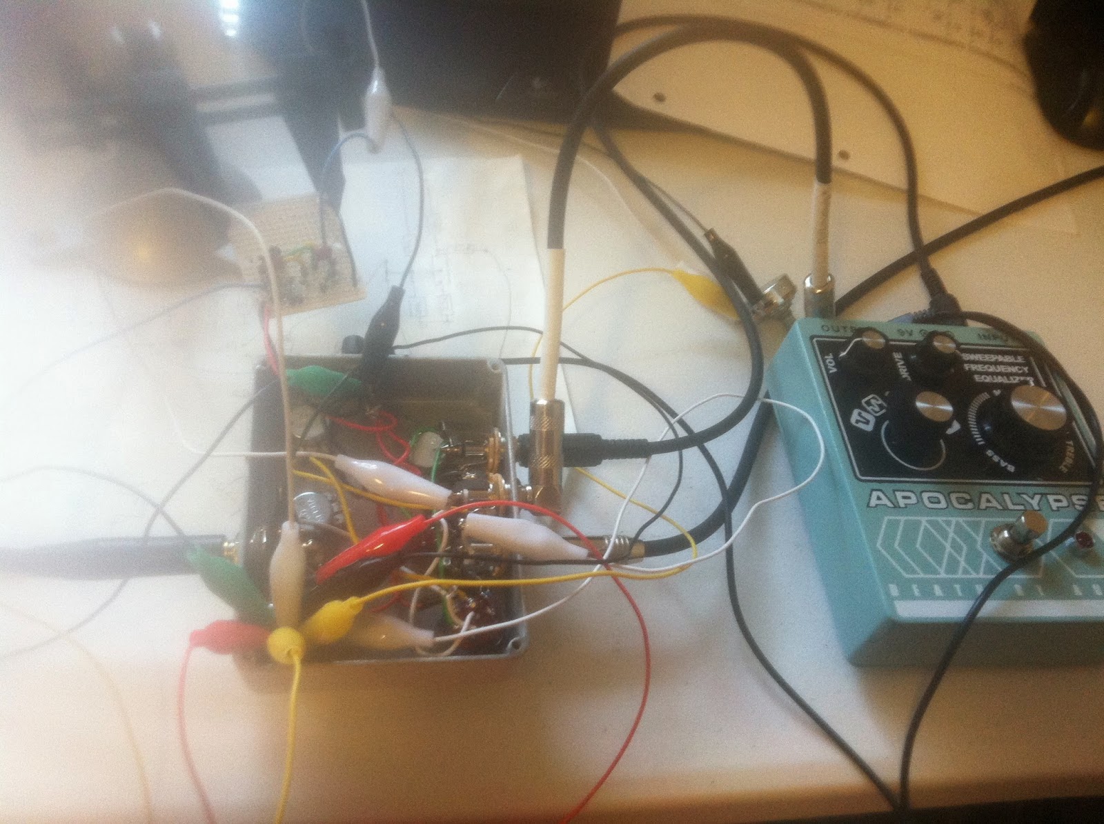
4.) Custom Dual Filter Overdrive 
I started with this pedal, but apparently grossly under-estimated my ability at soldering and layout on perfboard.  This is basically a big muff without the clipping diodes in the 1st fuzz stage and no 2nd fuzz stage with a footswitchable potentiometer to select the sweepable frequency equalizer.  I have the enclosure all drilled and tested some art, but it is basically non-functioning. And I might have to scrap a few parts because I burned them all out, slowly time will tell.


5.) Custom Big muff.
This will be the big project pedal that I work on this year.  I'd like to base it on the Supa tonebender with a rotary switch for the output sections, and a foot switchable filter. Each filter will have a rotary switch for tone bypass, as well as some of the other popular tone controls from the web.  I'd like to incorporate a lightplate too.


Well it's late and I need to get some rest before I can post other information regarding the pedal projects. I'll post the feedback pedal shortly as well as how I create the pedal artwork..