MONSTER DECIMATOR
Alright, here we have my first pedal ever!!! As I stated in the previous post, this pedal is based off of the diagram associated with BeavisAudioResearch. Although strangely it is no longer posted on his site. If you're curious about it just search "feedback pedal" and you should come across it.
The main thing about his diagram is that it has a SPDT switch for feedback versus true bypass loop. I wanted to incorporate all of the original diagram with some additional upgrades that I've seen from the Total Sonic Annihilation. Basically I wanted to incorporate a volume knob, as well as a boost. The volume knob was fairly simple. I combined a diagram from the true bypass loop with the feedback loop. For the most part, a lot of volume knobs appear to be 100k potentiometers going from the output of the circuit with the sweep to the output jack, and the 3rd leg going to ground. Insert this at the end of a pedal and Voila you've gained the ability to reduce the pedal output. In this case it limits the feedback/bypass loop output. The other part I wanted to incorporate was a boost circuit. For this I just used the LPB1 circuit that you can find all over the place. I couldn't determine whether I wanted it before or after the loop. In hindsight I think I could have wired a DPDT switch to switch between before or after the effects loop.
To begin with, I started with just the feedback/bypass portion of the circuit to test things out....

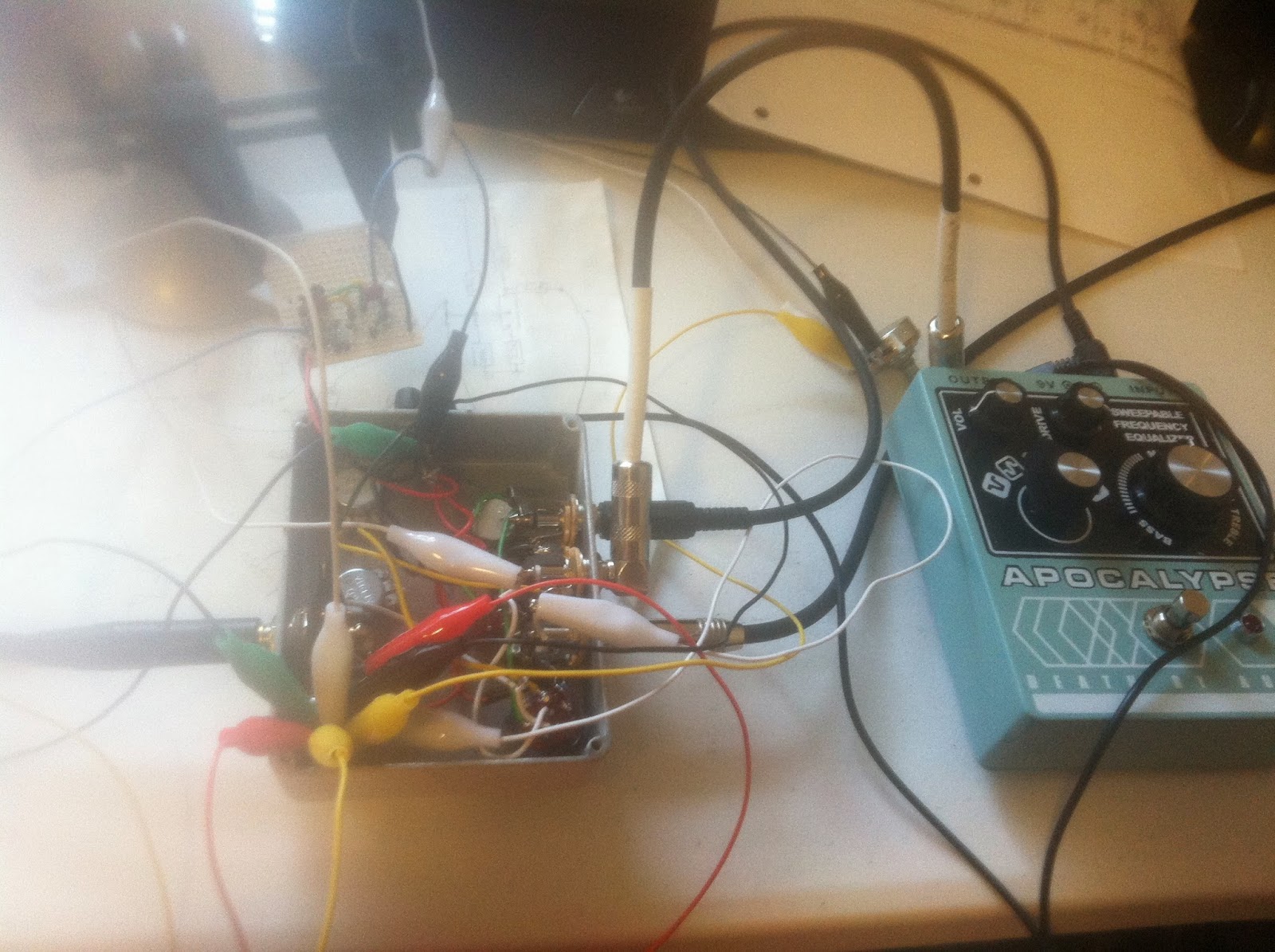
Here are the guts of the diagram with the volume knob wired in. I know it looks messy, but somehow I was able to keep track of how things were wired up. Please note the electrical tape that was used....very indicative of my amateur approach. I don't feel comfortable by any means working with wire or solder, and because of that I used a large amount of excess wire. This didn't cause as much of a problem as I thought, it just made soldering the boost potentiometer a little difficult.

So the next thing I had to do was test out the boost circuit. I didn't document the process as well as I could have, but I use a socket on everything, just about everything. I know its suggested for transistors, but I did it for the capacitors and the resistors as well. Turns out I put it at the end of the pedal. This basically makes the boost effective when the true-bypass loop is selected. Alligator clips come in handy as long as you have a good number of colors that you can keep track of. I used Adafruit's permaproto PCBs for the boost circuit. After failed attempts using perfboard, I figured if I used a breadboard and then the permaproto board I could match things up and make sure both circuits worked. This worked out for me excellently, although I didn't need to use half of the PCB. Live and learn am I right? After finalizing the wiring in the pedal, I put electric tape on the back of the permaproto board and "stuffed" it in the enclosure. Of course I tried all the "rock it before you box it" tests before I sealed it up.
I'll post a video of what it can do shortly, but in the meantime here is a picture of what it looks like. I'll try and draw up a schematic for it as well. On that note, It has been tricky for me to learn about schematics, but I've figured a good bit of things out, and with practice I'm sure any other hobbyist can learn as well. In fact I think I'll make a page for schematics only, as well as how I make the designs as well, just in case anyone is interested.

No comments:
Post a Comment